Intro
As an avid saltwater fisherman, I’m always searching for ways to improve my game, both on and off the water. Owning both a 3D printer and a CNC router, I decided to take on a new challenge: designing a modern remix of a classic striped bass lure—the Pikie.
A bit of history: The Pikie lure, originally designed by the Creek Chub Bait Company in the early 1900s for freshwater fishing, became a favorite among striped bass anglers along the U.S. East Coast by the mid-20th century. Its lifelike baitfish profile, durable construction, and versatile wobbling action made it particularly effective at mimicking prey like bunker and herring, turning it into a go-to lure for surfcasters targeting big stripers.
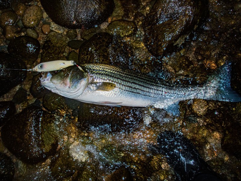 Striped Bass that fell for irresistable wobble of the Pikie - Image from On The Water
Traditionally, the Pikie was made from buoyant wood like basswood and shaped on a lathe. For my version, I’ll be using 3D printing for prototyping and a CNC router for final production. Since these manufacturing methods differ from the original, I’ll need to design the lure body in two halves and join them during post-processing. This approach offers advantages: it allows me to experiment with internal cavities for creating air pockets to boost buoyancy or adding weights to fine-tune the lure’s action.
In this post, I’ll outline my design requirements and the considerations I’ve made with Design for Manufacturing (DFM) in mind. I’ll walk you through my design process, share the lessons learned along the way, and discuss the next steps as I move toward prototyping my remix of this iconic lure.
Design Requirements
- Thru-Wire Construction - Ensures that a hooked fish stays on even if the lure body breaks, providing durability and reliability.
- Target Weight: 1-3 oz - This weight range is optimal for my preferred surf fishing setup, offering a balance between casting distance and control.
- Buoyant in Saltwater - Designed to float, allowing for surface action with the flexibility to tune for subsurface performance when needed.
- Parametric 3D Model - A fully parametric design for easy adjustments to the lure’s shape and profile, streamlining iterations and experimentation.
- 3D Printable - Optimized for rapid prototyping and testing, allowing for efficient tweaks and on-the-fly improvements.
- CNC Machinable - Tailored for transitioning proven prototypes to a CNC workflow, making it production-ready for higher-volume or more refined builds
Design Process
Material Selection
I will be using PLA filament for 3D printing the prototype of this Pikie remix for a few reasons:
- Easy to Print (minimal quality issues)
- Faster to Print (this material can run near the upper limits of my printer)
- Non-critical mechnical properties - I will be coating this in epoxy resin to make it water tight and more durable for testing - There is one important caveat; however, PLA is more dense than wood
A little bit of physics and math is needed to ensure my design will float in saltwater like a traditional pikie made out of basswood.
The density equation is:
where:
- is the density,
- is the mass,
- is the volume.
Here are the densities that will need be evaluated:
| Material | Density |
|---|---|
| PLA | 1.240 |
| Basswood | 0.320 |
| Saltwater | 1.025 |
At first glance, it appears PLA will sink in saltwater and basswood will float, but there are two levers that can be tweaked to target a specific density — mass and volume. The volume in this case will remain constant because the same lure shape/profile will be used for both materials. On the other hand, the mass can be adjusted on the PLA version to ensure it will float in saltwater.
To explain how this can be done, I will need to walk through the CAD modeling of the design and highlight some of the nuances in additive manufacturing that can help solve this problem.
CAD Modeling
The design was built in Fusion360, taking full advantage of its parametric modeling tools. Before drawing a single sketch, I set up a user parameters table with key values like body length, max body diameter, taper ratios, and thru-wire diameter. This upfront investment means future iterations — scaling the lure from 6” to 7”, or adjusting the taper to change swimming depth — require nothing more than updating a few numbers.
Body Profile
The Pikie’s signature silhouette — a tapered body with a widened mid-section — was modeled using a series of lofted profiles along a central spine. Each profile is driven by the parametric table, so the overall shape can be stretched or reshaped without rebuilding the model from scratch.
Solving the Buoyancy Problem
Returning to the density math from the previous section: for the lure body to float, its effective density must stay below 1.025 g/cm³. A solid PLA body at 1.240 g/cm³ won’t cut it — but Fusion360 gives us a clean solution: shell the body.
By designing the lure with a hollow core and uniform wall thickness, the effective density becomes a function of the shell volume rather than the total envelope volume:
Rearranging, the shell must occupy less than about 83% of the total body volume for the PLA body to float bare:
In practice I need a comfortable margin below that threshold to account for hardware weight — the thru-wire, hook hangers, and any ballast. I modeled the shell at a wall thickness that targets an effective body density well below 1.0 g/cm³, leaving headroom for hardware and future tuning.
Two-Halves Split
The body is split along the horizontal centerline — a flat parting line running the full length of the lure. This is the same concept used in injection molding: the parting line must be chosen so neither half has features that would trap the tool or prevent the part from being removed. For the CNC version, this means no undercuts — every surface must be accessible from directly above. For 3D printing, the flat parting face also minimizes the need for supports, keeping surface quality high.
Thru-Wire and Hardware
A U-shaped channel runs along the centerline of each half to house the thru-wire from nose to tail. Hook hanger positions are parametrically defined points along the spine, driving the placement of wire loops or eyelets during assembly.
Alignment
The two halves are registered by press-fit alignment pins distributed along the parting face, sized to the dimensional tolerances I’ve been able to achieve reliably on the Ender3. The tighter accuracy of the Shapeoko should make these fits even cleaner on the CNC version.
Learnings
Challenges
Capturing the Pikie Profile
The original Pikie has a very specific cross-sectional shape that produces its distinctive wobble. Translating that organic, lathe-turned profile into a parametric sketch took several iterations — I leaned heavily on reference images and measurements from published plug-building guides to get the taper and belly dialed in.
Designing for Two Manufacturing Processes at Once
The dual-process requirement imposed constraints that occasionally pulled in opposite directions. CNC toolpaths require minimum corner radii dictated by the end mill diameter; sharp internal corners that print cleanly on an FDM printer need to be radiused for the CNC workflow. Balancing both sets of constraints without compromising the swimming profile required careful thought about which features could be shared and which needed process-specific workarounds.
Thru-Wire Channel Alignment Across the Parting Line
Getting the wire channel to align perfectly across both halves — especially at the nose and tail where the wire exits the body — required precise feature mirroring in Fusion360. Any misalignment would bind the wire during assembly and create stress concentrations at the exit points.
New Skills
Fusion360 User Parameters
This was my most thorough use of Fusion360’s user parameters table to date. Building a fully driven parametric model from the ground up — rather than retrofitting parameters into an existing sketch — made it dramatically faster to explore shape variations.
DFM Across Multiple Processes
Thinking through Design for Manufacturing for both additive and subtractive workflows simultaneously was new territory. It reinforced the habit of asking “can both machines make this feature?” before committing to geometry — a discipline that should pay dividends on future projects.
Ready for Prototyping
After several rounds of iteration the design is locked: a 6-inch body split along the horizontal centerline, wall thickness tuned to keep the effective body density well below the saltwater threshold, a full-length thru-wire channel, and three hook hanger positions. The parametric model means scaling to a 5” or 7” variant is a single parameter change away.
Next up is Part 2: printing the first prototype on the Ender3, post-processing with epoxy resin for water resistance, assembling the hardware, and — the moment of truth — getting it in the water to see if it floats and swims the way the model predicts.
Conclusion
The design phase of this project was a reminder that even a “simple” fishing lure is a surprisingly nuanced engineering problem. Buoyancy math, DFM trade-offs, and the constraints of two manufacturing processes all had to be balanced before a single piece of filament was laid down. The parametric model is the insurance policy that makes all of that iteration tractable.
If you’ve built your own lures or experimented with 3D-printed or CNC-machined fishing tackle, I’d love to hear how you approached the design — especially around buoyancy tuning. Drop a comment below or reach out directly. And if you’re curious how the prototype turns out, stay tuned for Part 2.